POWER SUPPLIES
A. Demo Fusor:
A demonstration fusor’s power supply requirements are relatively easy to meet. It should provide a variable zero to ten thousand volts, with a current capability of around ten to thirty milliamperes. Less voltage and current is acceptable, more (voltage anyway) would be desireable.For our demo fusor, we used a neon sign transformer, rated at 15,000 volts and 30 milliamperes. These transformers are center-tapped, and the tap is grounded. A full-wave rectifier was built to rectify the A.C. to D.C., using diodes from a damaged X-ray power supply’s bridge rectifier. The X-ray bridge rectifier had been rated at 150 KV and 1 ampere, and used 4 diodes in series in each leg of the bridge. We used just two of the diodes for our full wave rectifier.
The rectified high voltage was filtered (somewhat) by a 30 nanofarad, 35 KV pulse capacitor which happened to be available.
A variac was used to vary the output voltage of the power supply from zero to about 10,800 volts.
UPDATE:
The center tap of the neon sign transformer was effectively disconnected from ground, and a full wave bridge rectifier connected across the entire 15,000 volts, as described by Andrew Seltzman on his web page. The same capacitor was used for filtering, and the positive terminal grounded. The output voltage range is now from zero to minus 22,000 volts (open-circuit). The output is current-limited with 70 K of resistance. One drawback is that we are now seeing x-rays being produced any time that the voltage applied to the fusor is greater than about 13 to 15,000 volts.
High Voltage Power Supply shelf, protected by a plexiglass enclosure.
From the right:
*The high voltage transformer with center tap ground removed.
*Oil-filled container with the full-wave bridge rectifier, voltage divider (for
metering) and a shunt for current metering.
*Rectangular white pulse capacitor being used as a filter capacitor.
*Current limiting resistors.
B. Power Supply for Actual Fusion:
The ideal supply would be capable of supplying a variable zero to 40 thousand volts, or even zero to sixty thousand volts, at a current of 25, or even fifty milliamperes. As a minimum, it should be capable of zero to thirty thousand volts, at an absolute minimum of ten or fifteen milliamperes.The most likely course for us to follow would be to obtain an x-ray transformer, and build the power supply around that. Unfortunately, most dental x-ray transformers (the type most commonly available) don’t really have the current capability that we would like, so we are looking for something bigger. Unfortunately, they tend to be monsters, weighing 250 to 300 pounds!
The large variac that we currently use to control the power supply output should work just fine with an upgraded power supply, and our high voltage rectifiers should also be okay.
UPDATE – December 2006:
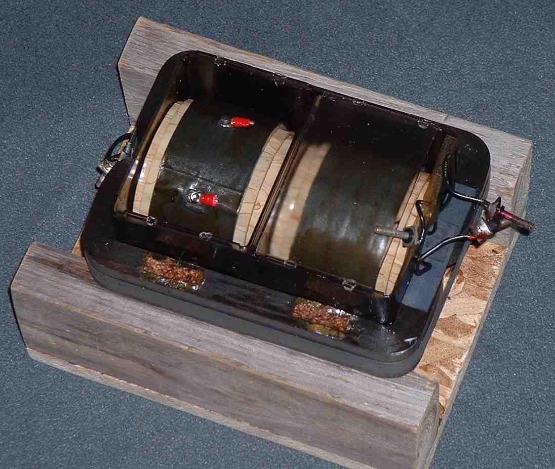
Our newly purchased X-ray Transformer, sitting in a temporary wooden cradle. The claimed ratings are:100,000 volts (peak) at 30 mA, but it will be used as a center tapped 50 KV-0-50KV source, full wave rectified to give unfiltered 50 KV D.C. The rated input is 110 VAC (RMS). With the input fed from a variac, the output will be variable from 0 – 50 KV (peak). The unit, along with its rectifiers, metering resistors and current limiting resistors, will have to be submerged in oil.
At the suggestion of Jon Rosenstiel, we are also planning to use inductive ballasting in the primary circuit. Jon suggested the use of a neon sign transformer primary in series with the x-ray transformer’s primary. The current limiting effect could then be reduced, if necessary, by shorting one or both halves of the NST’s secondary.Because of availability, we may initially try one or more microwave oven transformers for ballasting, instead of a neon sign transformer.
FURTHER UPDATE – September, 2007:
The completed power supply is shown below. The transformer, rectifier, metering resistors and current limiting resistors are all in the same container, under oil. The primary of a single microwave oven transformer, with the output of it’s secondary shorted, is placed in series with the x-ray transformer primary winding, to act as a current-limiting ballast.
The Complete X-Ray Transformer-Based Power Supply:
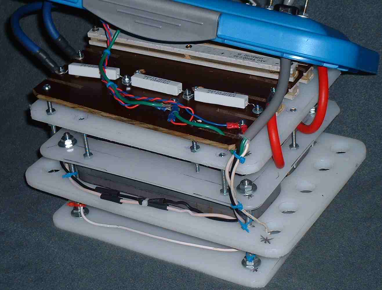
The complete assembly ready to be submerged in oil.
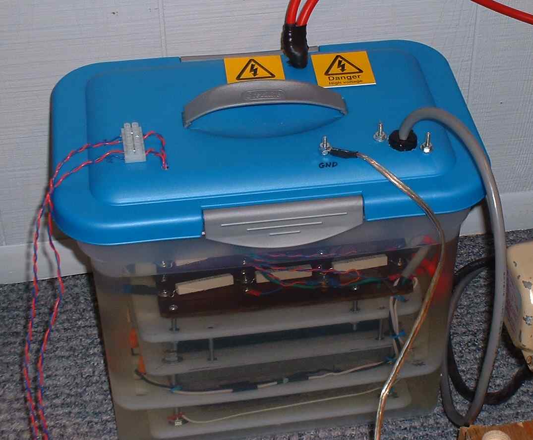
The completed unit in its WalMart container, and ready to power the fusor.
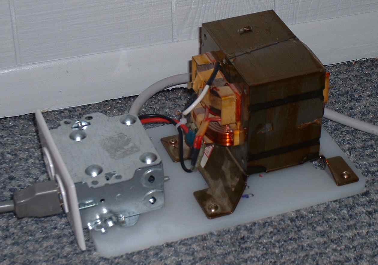
The microwave oven transformer-based ballast. Its primary winding is in series with the primary of the x-ray transformer. Its secondary is shorted.
Power Supply Schematic
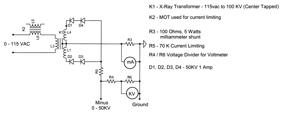
Power Supply Schematic – Additions & Changes
For additional safety margins, there are now 3 diodes in series in each leg of the rectifier, instead of 2.
R4 consists of three 100 Meg precision resistors in series, to give 300 Megohms total.
R6 consists of three 10K 5 watt resistors in series, to give 30 Kilohms total.
(R4 and R6 make up a 10,000:1 voltage divider used for measuring the High Voltage.)The secondary of K2 is shorted.
![]()
