 |
|
|
|
|
|
|
|
|
|
|
|
|
|
|
|
|
|
|
|
|
|
|
|
|
|
|
|
|
|
|
|
|
|
|
|
|
|
|
|
|
|
|
|
|
|
|
|
|
|
Equipment/Supplies Pg 1 |
|
|
|
EQUIPMENT / SUPPLIES (Pg
2) |
|
|
|
BELL
JAR for DEMO FUSOR |
|
|
|
To use a glass bell jar for a
fusor, the glass must be pyrex. Otherwise, a stray electron or ion
beam causing localized heating of the glass, can result in an
implosion. Pyrex bell jars of a reasonable size are not infrequently
seen on Ebay, but unfortunately we couldn't find a seller willing to
sell outside of the USA. Persistence paid off, though, and eventually
we obtained a 12 inch diameter by 12 inch high pyrex bell jar from a
Canadian seller. |
|
|
|
Base |
|
|
|
A fourteen inch square piece of 1/4
inch thick 6061 T6 aluminum was obtained locally. The edges and corners
were rounded and polished. 1 inch and 1 1/2 inch hole cutters were
purchased, and the required holes cut through the aluminum using a
drill press. The 1 1/2 inch hole was cut in the center for the high
voltage feed-through, and two 1 inch holes cut for the vacuum pump
connection and for the vacuum gauge sensor.
Bulkhead fittings were used to attach the vacuum lines (QF25) and the
high voltage feed-through (QF40). Each of the three bulkhead fittings
is fastened to the base by stainless steel 6-32 screws, using tapped
blind holes. The holes had to be at least 3/16 inch deep, but not
penetrate the upper surface of the aluminum. Using a 3/8 inch aluminim
base instead of 1/4 inch would have made this operation a lot less
harrowing! Finally, mounting holes were through-drilled in the 4
corners of the base plate.
The entire base plate was then polished, and finally cleaned with
acetone.
The base was then mounted about 8 inches above a scrap plywood base,
using 1/4 inch all-thread rod, with pieces of 1 inch PVC tubing used as
spacers. |
|
|
|
Bell
Jar to Base Seal |
|
|
|
We simply used a generous layer of
vacuum grease on the ground glass sealing surface of the bell jar to
create a seal with the base plate. This works well, except that
whenever vacuum is removed from the system totally, even if the bell
jar is not disturbed, the seal is lost. The bell jar then has to be
removed, and the surface re-coated. |
|
|
|
Electrical
Feedthrough and Support for Inner Grid |
|
|
|
A
20,000 volt Electrical Feedthrough with a QF40 flange was purchased
from Kurt J. Lesker. This was purchased with its final use in the
actual fusor in mind. A higher voltage rating would have been
desireable, but cost was an issue. It was felt that with care, and good
high voltage practices, the feedthrough could be used at much more than
its rated 20,000 volts.
Time will tell whether or not this was false economy!
The photo on the right
shows the inner grid supported on the end of the inner conductor of the
feedthrough. An insulating tube of alumina ceramic (available from
McMaster Carr) has been slipped over the conductor, and protects it
from ion bombardment.
In the photo, the bell jar and the outer grid have been removed. The
discolouration of the metal base is due to electron and ion
bombardment. (For the same reason, the bell jar itself now gives the
impression that it was made of smoked glass!) |
|
|
|
 |
|
|
|
|
|
BELL
JAR MODIFICATIONS FOR FUSION EXPERIMENTS |
|
|
|
With
higher voltages and currents required for fusion, it was obvious that
something like a stainess steel enclosure had to be built within the
glass bell jar to protect it. However, a glass covered opening in the
stainless enclosure would be required to allow the poissor to be viewed. |
|
|
|
Below
Left is the large stainless steel
cooking pot that was modified to make a protective shield within the
bell jar. The handles were removed, the lid discarded, and a 2 inch
circular hole was cut into the base. |
|
|
|
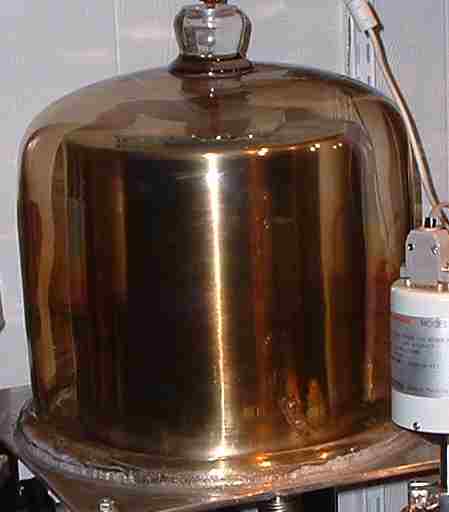
Below
Right is the completed bell jar, ready
for fusion experiments. Inside is the stainless pot, upside down, with
the 2 inch hole now facing up and covered with a square of 1/4 inch
glass. This allows the webcam to view the interior while protecting the
bell jar from stray electron beams. The 1/4 inch glass gradually
darkens and has to be replaced, which of course involves opening the
bell jar. |
|
|
|
 |
|
|
 |
|
|
|
|
|
Vacuum
grease was used as a seal between the
bell jar and the base plate. In the photo on the right, the excess
vacuum grease can be seen around the base of the bell jar. |
|
|
|
|
|
|
BUILDING
THE INNER AND OUTER GRIDS |
|
|
|
 |
|
|
(RIGHT)
Inner and outer stainless steel
grids under construction.
The inner grid shown is the one used in our initial demonstration
fusor. Both inner and outer grids were made by first welding the
individual rings, and then welding the rings into a grid.
The inner grid currently in use is slightly smaller than the one shown. |
|
|
|
|
|
|
"Equipment
to Build the Equipment" - A Homemade Spot Welder |
|
|
|
The inner grid of a fusor is
usually a spherical shape, and usually created from wire. Although
silver-soldering can be used to form the wire into a sphere, the most
popular way is to use resistance welding (spot welding). Unfortunately,
most commercially made spot welders are designed for much larger
material than the approximately .030 stainless steel wire that we
wished to use. We therefore built a simple welder ourselves. The heart
of our welder is an assembly of 14 - 4700 ufd, 50 volt electrolytic
capacitors in parallel, for a total of 65800 ufd. A simple
transformer-rectifier is used to charge the capacitors, through an
inrush-current limiting resistor.
Discharge is controlled by a small contactor salvaged from a very early
Amana Radar Range microwave oven. To reduce the instantaneous current
when the contactor closes, the output goes through an inductance made
by winding #10 wire onto the core of a salvaged microwave oven
transformer. This is necessary because the electrolytic capacitors are
not designed to withstand extremely high instantaneous discharge
currents. The discharge energy can be controlled by varying the voltage
that the capacitors are allowed to charge up to.
Discharge Electrodes were formed in several different shapes, from
several sizes of copper pipe and tubing. An anvil made from a copper
pipe tee and end cap can serve as one of the electrodes. A pair of
clothes pegs with copper jaws was mounted to hold pieces of wire that
need to be joined end to end.
The apparatus is assembled on a pair of wooden bases, and although not
pretty, it does a credible job of spot welding the stainless steel wire. |
|
|
|
 |
|
|
|
(LEFT) The cobbled-together
resistance (spot) welder. On the left base is the (small)
25 volt transformer, bridge rectifier, and the storage capacitors. The
large "transformer" is the current-limiting inductance, and to its left
is a small contactor used to control the output.
On the right is the base for the anvil and electrodes. The large black
microswitch is used to control the contactor. |
|
|
|
|
|
Home
Page |
|
Equipment/Supplies Pg 3 |
|